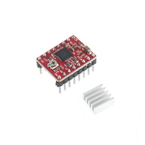
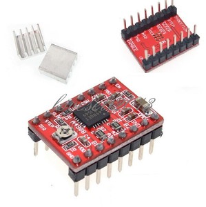
Can you have SoundTrap recorders as carry-on luggage in a plane? I just tried connecting the gnd to the arduino, but it didn't work. same was the case with 2a, 2b output ports. Ok so now we get to the likely reason why Stepper Drivers die. This breakout board for Allegros A4988 microstepping bipolar stepper motor driver features adjustable current limiting, over-current and over-temperature protection, and five different microstep resolutions (down to 1/16-step). If that is too low it would explain why nothing happens. Then i connected my bipolar stepper motor, which has 4 wires to the ports 1a 1b 2a and 2b. i tried connecting the vcc and gnd of a4988 to arduino board but it didn't workout. @justone
/yaootaweb-production/media/crawledproductimages/8bad5e860c8df19a92213b92a136873d22f3eed8.jpg)
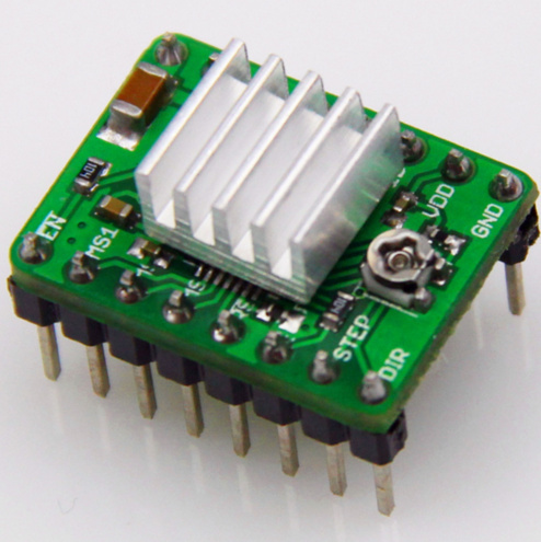
If you touch the motors during a very long print, you will notice that they can get quite hot. Just make sure to keep it dust and dirt-free. The following picture shows how to identify which current sense resistors your board has: Identification of original 50mO sense resistors (left) and 68mO sense resistors (right) introduced in January 2017. Is it permissible to walk along a taxiway at an uncontrolled airport to reach airport facilities? Take a look at ourcustomer service pageif youhave other questions such as "do we do purchase orders" (yes!) I am only going by the picture you posted concerning the hookup of the ground. I don't know why but it has to be like that. By clicking Post Your Answer, you agree to our terms of service, privacy policy and cookie policy. If the power source terminals are not delivering the necessary voltage, the printer components will start to fail. My switch going to the bathroom light is registering 120v when the switch is off. In contrast to changing some obscure setting in the slicer, my heart tends to skip a beat when Im dealing with mechanical and electrical parts. In his video you see that the sleep and reset pins are connected. As i bought it from ebay.in i can return it within 7 days . Both receive voltage. i did the same with the other coil. @PurpleOwl See the answer below, that's what I tried and it worked for me. Use tab to navigate through the menu items. The A4988 driver IC has a maximum current rating of 2A per coil, but the actual current you can deliver depends on how well you can keep the IC cool. You are not showing any connection to the Arduino ground. Exact shipping can be calculated on the view cart page (no login required). I recently bought a clone A4988 driver, but they were faulty. The current is set too low on the board (screw on the motor driver). Well, it's true that I bought this front eBay.in and this doesn't look like a clone. If so it's possible there are differences. So i made the connections like this. You see Stepper Drivers provide current to each coils of a Stepper Motor and those current are switched back and forth to make the Stepper Motor rotate. This small board regulates the power of the stepper motor and it serves as the link between the control board and the stepper motor. We specialise in DIY electronics, desktop manufacturing and educational technology.

Common BreadBoards are made to accept solid core wire of around 0.6mm or 24AWG size to guarantee a good and reliable connection. or "are prices GST inclusive" (yes they are!). The library has functions that enable users to set rotational rate, change microstepping mode, and specify how many steps to take or specify how many degrees to rotate. The most common cause of loss of steps in the movement axes is a low voltage set in the motor driver. If you feel that my Videos /Tutorials are helping, and you would like to contribute You can toss some coins in the Tip Jar via PayPal. Thanks again :), Stepper Motor is not working with A4988 board, How To Control a Stepper Motor with A4988 Driver and Arduino, Measurable and meaningful skill levels for developers, San Francisco?
It applies to both the green (md09b) and black (md09c) editions of the A4988 stepper motor driver carrier. But the motor was not moving. i connected my arduino mega to my laptop via USB cable provided with the board. A couple of things can lead to a Stepper Driver not working. On Marlin-type printers, select Prepare -> Move axis and select the axis of the motor that is not working. This is just wasting everyone's time, yours included. Stepper Drivers, like the Easy Driver, are required to drive Stepper Motors since the Arduino itself cannot provide anywhere near enough current to drive them.

Was Mister Kitson and/or the planet of Kitson based on/named after George Kitson? First of all, you must check that the motor receives electrical current. Which lead should I buy for my DC power supply? having problems with my arduino bluetooth car project(with L298n Motor Driver), Stepper motor slow when reading from MPU 6050 sensor, Stepper motor driver not working properly. By clicking Accept all cookies, you agree Stack Exchange can store cookies on your device and disclose information in accordance with our Cookie Policy. When the light is on its at 0v, Governing law clauses with parties in different countries, Is it possible to turn rockets without fuel just like in KSP. When connecting the Stepper Motor to a common Stepper Driver like the Easy Driver you will probably using a BreadBoard to make the connection between the two. i really didn't connect the arduino gnd.
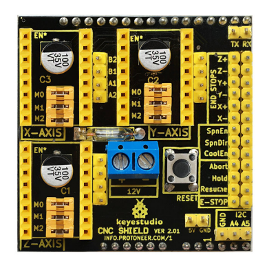
International Orders - the following rates are for New Zealand and will vary for other countries: If you order lots of gear, the postage amount will increase based on the weight of your order. Well i think that some or the other component of a4988 is not working. 468). A short video showing the in-house assembly of a panel of Black Edition A4988 stepper motor driver carriers on Pololu's Samsung SM421F pick and place machine. please correct me if i am doing something wrong. Be very careful when connecting the driver, as its pins must be oriented correctly (look for the Enable pin on both the driver and the board and match them). @Robin2 3dsolved.com is a participant in the Amazon Associates program and may earn commissions on qualifying purchases. Now that we are aware of this, lets try to fix that annoying motor! Thanks! It is sufficient to connect sleep and reset to each other. In case you need to replace a driver, you will not have to redo this test. and then i connected VMOT to +12V and the respective ground. Altough I think I know my way around a 3d printer, it always scares me when a machine fails due to a potential hardware issue. then i checked the voltage difference between direction and step(just like that :P). Over the years Ive done many projects and tutorials using Stepper Motors and of course that includes Stepper Drivers. As I have described in my first post(refer to that post), that I have tested the motor, which seems to be Fine but I can't be 100% sure. RepRap 3d printers often use an Arduino Mega + Ramps combination as they are the cheapest and most reliable version you can get. But when he hooked up the ground it didnt fix it so that makes it not necessary. And I am pretty sure that I did exactly the same. Since I started taking those steps when working with stepper drivers, I havent had a stepper driver malfunction. So i bought Nema 17 stepper motor, Arduino Mega and the stepper motor driver a4988. This product can get hot enough to burn you long before the chip overheats. You have to connect the sleep and reset pin together. As a rule of thumb, we could say that if you cannot touch the stepper motor, it is because it is clearly too hot. ~Sleep is an input, as is ~Reset, and both must be tied to Vcc otherwise - no cheese! i have tried everything that was posted here, please correct me if you think that i didnt do exactly as told. RCSV_(REF) = 8 * I_(MAX) * R_(CS). Revised manuscript sent to a new referee after editor hearing back from one referee: What's the possible reason? Check the voltage supplied by the source with a multimeter. I have NOT. I used one of the examples of the arduino, which i uploaded to it and it was working fine. There is no need to connect the MS pins. If you use hairspray to improve bed adhesion, be sure to cover all the electronic parts before spraying it. How is making a down payment different from getting a smaller loan? Well from the starting only I did the right connection so that I don't destroy anything. The EasyDriver boards are different from the Pololu boards, for example. Again I am saying that I think the stepper driver is faulty. The Pololu website explains how to adjust it. Within this range of engines, there are countless variants that may or may not match the specifications you need. I even tried many different programs, but none of them worked. Since the input voltage to the driver can be significantly higher than the coil voltage, the measured current on the power supply can be quite a bit lower than the coil current (the driver and coil basically act like a switching step-down power supply).

This technology never ceases to amaze me, and I always thrive to stay up to date with the newest trends in the space. Please continue if you would like to leave feedback for any of these topics: For all other inquiries (orders status, stock levels, etc), please contact our support team for quick assistance. Now it is time to check the control board. The 3d printing community is like none other I've seen before, and writing these articles and coding (somewhat) useful tools is my way to contribute at least a bit!
Sooner or later, you will have to deal with a stepper motor not working correctly. If you set the power supply higher than 30 volts that can kill a stepper driver pretty quickly. The soldering in your pictures does not look good and there are many joints that are not making good enough contact with the pads, so we should address that first. I have the same problem. You were told to connect the ground several posts back. Then i copied the program for one of the sites and uploaded that program to the arduino mega. Nema 17 only tells us the physical size of the front face. Replace the power supply if necessary. Those wires are cheap and easy to find almost anywhere (amazon, aliexpress, etc) commonly named Dupont wires. Disconnect the power supply from your project, make sure that the voltage is set to the right amount, turn it off, and then, connect it to your project. Core Electronics is a maker education and retail company based in Newcastle Australia. If you think it is defective then please reply fast so that i can return it back(i bought it from ebay.in). First of all, i wanted to tell everyone that i am a mechanical student so don't know much about electronics. It doesnt use any library so it should be very easy to follow. Site design / logo 2022 Stack Exchange Inc; user contributions licensed under CC BY-SA. :~ Please help me with this problem. Then i connected pin 13 of the board to the direction pin of the a4988, pin 12 to the step pin of a4988. I recommend using the Adafruit Guide to Excellent Soldering as a reference for improving that. The best answers are voted up and rise to the top, Start here for a quick overview of the site, Detailed answers to any questions you might have, Discuss the workings and policies of this site, Learn more about Stack Overflow the company, Have you tried pulling Sleep and Reset to HIGH, like shown on page 1 and 7 of the. rev2022.7.29.42699. Although we are going to dig deeper into each cause, these are the most common causes of a stepper motor not properly working. Regulate the voltage in the drivers at a midpoint, in which the operation is as expected but without increasing the temperature too much.

For example the Easy Driver can take voltage from 6 volts to 30 volts. Arduino Stack Exchange is a question and answer site for developers of open-source hardware and software that is compatible with Arduino. You say you bought it on Ebay - does that mean it's a clone rather than a "real" Pololu board. Connect and share knowledge within a single location that is structured and easy to search. We're here to help! the connections that i made are the same as shown in the circuit diagram. i don't know what do do with those pins. There is no way to know from this distance whether it is definitely faulty. This DXF drawing shows the locations of all of the boards holes. This is the code(it's simple): When I connect the sleep and reset pin on the A4988 board the stepper motor starts turning. So now everything is available in this day and age, and all those childhood dreams ca For the best experience on our site, be sure to turn on Javascript in your browser. Follow the wiring diagram that was posted earlier. What current setting is the board set for? I have a similar problem where it turn in one direction and only when the pwm signal goes throught the direction pin instead of the step pin. then between vmot and the gnd, it was 12v. Then, if the motor vibrates or click, it may be one of these problems: If it's not one of those problems, the A4988 chip might have an issue. A 3D printers stepper motor may not be working due to insufficient electrical current, a loss of continuity along with the wiring or a connector, or a faulty stepper motor driver or control board. When prototyping a project, youll be most likely using the type of wires you see in the picture above. Although the specific values varies quite a lot, it usually falls in the 70C-100C range.

The question is from about two years ago. Try checking the continuity of each wire using a multimeter (the video below shows you how to do it). Also, if the supply voltage is very high compared to what the motor needs to achieve the set current, the duty cycle will be very low, which also leads to significant differences between average and RMS currents. its the same smps which is giving +12v to the vmot for the motor. The next step in finding the cause for the failure is verifying the driver. One month later, I bought my first FDM printer and did not look back! You dont say what brand of A4988 driver you are using but I know the Pololu website has detailed wiring instructions for their board and I think Sparkfun also has. Like why? This Arduino library, written by forum member laurb9, allows users to control a stepper motor with Pololu's A4988, DRV8825, or DRV8834 carriers. Adafruit LSM6DS3TR-C 6-DoF Accel + Gyro IMU - STEMMA QT / Qwiic, version with male header pins already soldered in, bulk-packaged version without header pins, bulk-packaged version with header pins installed, Black Edition A4988 stepper motor driver carrier, version of this board with headers already installed, Allegro A4988 stepper motor driver datasheet, Dimension diagram of the A4988 Stepper Motor Driver Carrier, 3D model of the A4988 Stepper Motor Driver Carrier, A4988 Stepper Motor Driver Carrier drill guide, A4988 Stepper Motor Driver Carrier (Header Pins Soldered), HC-SR04 Ultrasonic Module Distance Measuring Sensor, A4988 Stepper Motor Driver Carrier, Black Edition, Metal DC Geared Motor - 12V 100RPM 42kg.cm, AL Heat Sink (With adhesive tape) - 13*13*7mm, Simple step and direction control interface, Five different step resolutions: full-step, half-step, quarter-step, eighth-step, and sixteenth-step, Adjustable current control lets you set the maximum current output with a potentiometer, which lets you use voltages above your stepper motors rated voltage to achieve higher step rates, Intelligent chopping control that automatically selects the correct current decay mode (fast decay or slow decay), Over-temperature thermal shutdown, under-voltage lockout, and crossover-current protection, Short-to-ground and shorted-load protection. What is your opinion. Your email address will not be published. Although it sounds silly, most problems are usually solved via almost trivial and very basic checks. so it has its own ground. If you are like me, you certainly prefer to do some research before trying potentially irreversible things. Failure in any of the wires will result in the engine not working properly.
So taking just a bit of time to solder the proper size wire to the stepper motor and being careful not to move your project when the power is on, just might save you some money in the end. You essentially need to connect the sleep and reset pin together. Using a ceramic tip screwdriver, turn the potentiometer clockwise. Try moving the driver to another plug and see if the problem is transferred to the engine where you connected that driver. Now of course over those years of playing around with Stepper Drivers, once in a while one of them would just stop working for no apparent reasons. Once you have a good configuration, I recommend that you take note of the values for each stepper motor. Please note that measuring the current draw at the power supply will generally not provide an accurate measure of the coil current.

( https://ultimachine.com/content/kysan-1124090-nema-17-stepper-motor )